Halo guys its been so cool finally Intel is comming next week to meet the hacker community in kenyatta university to introduce us to their new board called Gallileo
Many people have been asking me about what thet is i just want to give a brief intro about the board its features and com pare it with the Arduio that most of you know and also with resberry pi
After this am sure you wnt to get your hands on to thi cool board and build that cool project you have had in mind also Intel is running an interuniversity challange featuring Kenyatta universty,JKUAT and UON
INTEL GALILEO
This is an open source prototyping board built by Intel engineers together with Arduino engineers .It is designed in Ireland and was released in October 3 2013
The board is Aduino com partible meaning actually you can use the Arduino IDE to programm it like you do using Uno,Decimila etc
The Galileo is a micro controller board based on the SocX 1000 applicaton processor from intel
Its the first board that runs on intels architecture
Hello hardware hackers and enthusiasts today we want to continue with our arduino programming and opensource hardware programming trust me within no time you will be ready to build your robot,home automtion and other cool stuff
Today I want o take you gently on how to read from an analog sensor and display it in your pc
cool right this is a series that will teach you how to interface an arduino to the hardware nd lso begin to teach how to code it
REQUIREMENTS
Arduino R3 or any will work
jumper wires
LED to display the brightness according to the potentiometer value
potentiometer
an analog sensor like photoresistor, thermal sensor or thermister
jumper wires and some resistors
for information on the photoresistor check out my other blog
PROCEDURE
The potentiometer has three pins one in the centre and two other to the exteem left and right
connect the middle pin to the analog pin ieA0 of the Arduino this is because its an analog sensor or device
Thn connect the other pins of the potentiometer to +5v and GND of the arduino thats it very simple and easy to do for a beginning
launch your arduino and then copy this code below guys notice the code is afree one and it comes as examples with the Arduino IDE
CODE
The code for this example is here: as i said its in your ide but i just modified it kidogo
int potPin = 0; //Analog input pin "0" that the potentiometer is attached to
int potValue = 0; //value read from the pot
int led = 9; //PWM pin that the LED is attached to (note: PWM 0 is on digital pin 9)

void setup(){
  //initialize serial communications at 9600 bps:
  Serial.begin(9600);
  //declare the LED pin as an output:
  pinMode(led,OUTPUT);
}

void loop(){
  potValue = analogRead(potPin); //read the pot value
  analogWrite(led,potValue/4); //PWM the LED with the pot value
  Serial.println(potValue); //print the pot value back to the debugger pane
  delay(10); //wait 10 milliseconds before the next loop
}
Lets now use it to control the speed of a motor
ENJOY YOUR FEED BACK IS HIGHLY WELCOMED nice
Wednesday, 19 February 2014
ARDUINO AND ANALOG READING OF SENSORS
Monitoring the light intensity of your room and displaying it on your pc screen using a light sensor and arduino
Requirements
Arduino
led
LDR
2 resistors 330 ohm any value will work
connecting wires/ jumpers
breadboard or project board
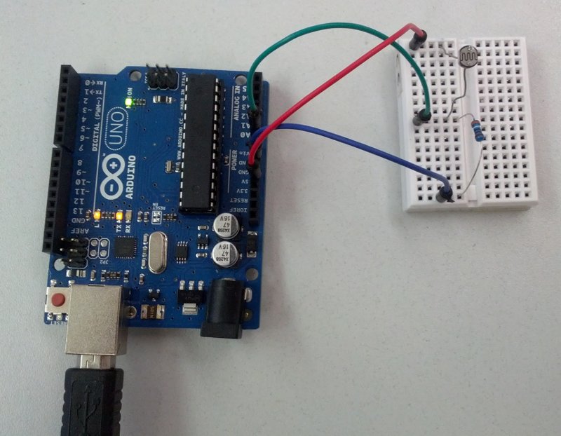
The procedure is very simple as follows
insert the LED to the bread board connect a 330 ohm resistor to the anode of the led (+ve) terminal then connect the resistor to pin 11 of the arduino (any pin with pwm will work)
place the LDR or photoresistor into the breadboard connect one of its terminal to +5v of the arduino
connect the other terminal to the second reistor and finally connect to the ground of the arduino use the ones in the analog side
at the point where the ldr connects to the resistor put a jumper wire and connect the junction to analog pin ero of the arduinoA0
finally connect the cathode of led to the grd of arduino
The code is also simple
int led = 11; // thi is where the led is connected to pin 11 of arduino
int photocellpin=0; //photocell or LDR is an analog sensor and is connected to analog pin 0 ie A0
int photocellReading;//
int ledbrigtness;
void setup() {
pinMode(led, OUTPUT);
Serial.begin(9600); // here serial communication with the laptop is established for monitoring //with the screen
}
void loop(void) {
photocellReading=analogRead(photocellpin); // and the sensor bieng analog is read with this //methord and its value assigned to the photo cell reading
Serial.print("Analog reading= " );
Serial.println(photocellReading);
if(photocellReading<=700){
digitalWrite(11,HIGH);
}
else{
digitalWrite(11,LOW);
}
delay(1000);
}
For guys like Odawa who are interested in sensors here is a small introduction to proximity sensors
Please try and modify your project with that succes card speaker and come and show us happy learning
Enjoy and the presentation will be done by Rose wawire and her friend your feedback is highly appreciated